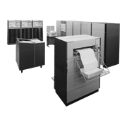
Mitsubishi Electric produced the MELCOM 7000 series through a technology-sharing agreement with the American firm XDS, in order to respond to the growing demand for mainframe computers. The series was announced in 1970. The MELCOM 7000 series consisted of the MELCOM 7500 and MELCOM 7700 models. One of the biggest distinction of the MELCOM 7000 series was its simultaneous support for four processing types: namely, batch processing, time-sharing processing, real-time processing, and remote batch processing. It was one of a handful of computers in the world, particularly in time-sharing processing, with sufficiently advanced functionality to allow up to 128 users to access and use the computer simultaneously. This functionality included dynamic relocation of programs and high-speed fixed-head magnetic disk units for swapping programs with data transfer speed of 3,000 kilobytes per second.
The system consisted of a main memory of up to 512 kilobytes in its center, and a central processing unit (CPU) and up to eight I/O processing devices connected to the main memory via memory buses.
The main memory consisted of up to eight memory modules, each of which could operate independently. Because of this independence, interleaving was used to assign addresses so the computer could access different memory modules when continuous addresses were accessed. The ability to overlap accesses reduced the effective main-memory access times and, thereby, boosted the computer’s processing speed. Addresses could be assigned using two-way interleaving and four-way interleaving. The main memory’s cycle time was 0.85 microseconds, but with interleaving, the main memory operated with an effective cycle time of just 0.56 microseconds.
The MELCOM 7000 series had 16 general-purpose registers for calculations, seven of which were used as index registers. The MELCOM 7500 could be expanded to 16 pairs of general-purpose registers and the MELCOM 7700 to 32 pairs of general-purpose registers. When multiprogramming, programs could be switched at high speed by allocating different registers to each program.
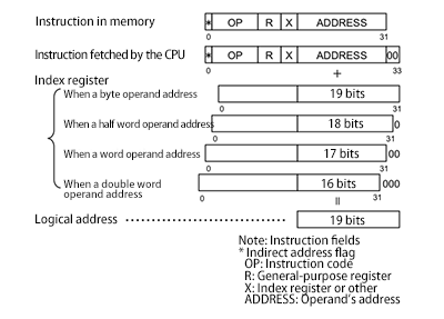
Addresses within instructions were word addresses. The index value indicated the displacement with the size of the instruction’s operand (byte, half word, word, or double word). As Figure 1 shows, the operand was converted to a displacement in bytes by shifting the index register’s value left by one bit if a half word, two bits if a word, and three bits if a double word. This was added to the 19-bit byte address which added two zero bits after the address in the instruction.


