【Mitsubishi Electric】 MELCOM 1101

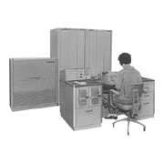
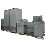
The MELCOM 1101, designed primarily for scientific and engineering calculations, was completed in 1960 and was Mitsubishi Electric’s first digital computer. It featured 33-bit words, static logic, binary serial operation, a stored-program architecture, and all-transistor circuitry. The clock speed was about 214 kHz. For its logic circuit elements, the MELCOM 1101 used about 3,500 germanium transistors and about 4,000 germanium diodes. The computer had 19 different types of epoxy printed circuit boards and was put together with a total of about 750 boards.

The MELCOM 1101’s basic configuration consisted of an arithmetic and control unit, a magnetic drum memory unit, and a control console. The control console was fitted with two photoelectric tape readers capable of reading 200 to 400 characters per second, one paper tape puncher with a punching speed of 1,200 characters per minute, one I/O typewriter, and a display and control panel. The external dimensions were as follows:

Arithmetic and control unit 1,800 x 700 x 800 mm (h x w x d)
Magnetic drum memory unit 1,100 x 1,000 x 800 mm (h x w x d)
Control console 750 x 1,650 x 800 mm (h x w x d)

It was possible to add to the basic configuration two more photoelectric tape readers, three more paper tape punchers, and four more magnetic tape memory units. The computer ran on 100 volts (±10 percent) single-phase AC at 50/60 Hz (±2 Hz) drawing about six amps or on 220 volts (±10 percent) three-phase AC at 50/60 Hz (±2 Hz) drawing about two amps. Because the MELCOM 1101 was designed around a building block structure, its functionality could be expanded dramatically by adding an arithmetic accelerator — dubbed FLORA, short for “floating point arithmetic accelerator” — and a digital differential analyzer (DDA).

The arithmetic unit, operating under the main control unit, had auxiliary controllers for input, output, and special calculations that could operate independently. This architecture meant that slow input and output processing and complex calculations, such as multiplication, division, shifts, and normalizations, could be run in parallel with easier additions, subtractions, evaluations of conditional statements, etc. With a certain amount of clever programming, the time to process calculations could be greatly reduced. For example, the INFO-3000 interpretive routine shaved between a third and a half off the time required to multiply or divide floating point numbers.

The delay-line memory drum used for memory storage had a capacity of approximately 4,000 words. It was about 30 centimeters in diameter and about 30 centimeters tall and operated at 3,600 rpm. The memory drum had independent read and write heads, numbering about 70 each. As the figure below illustrates, after data were read, they were passed through an external shaping amplifier circuit and immediately re-written to the drum by a write head. Immediately after being read, the previous memory location was demagnetized. This methodology created a line with a short wait time independent of the rotational speed. The memory drum was configured with 40 100-word lines (average access time of 7.8 milliseconds) as general-purpose memory and, as a high-speed memory, eight four-word lines (average access time of 0.31 milliseconds), six two-word lines (average access time of 0.16 milliseconds), and two one-word lines (random access).


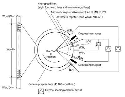
Figure: Magnetic drum’s principle of operation

Figure: Magnetic drum’s principle of operation

Each machine language word consisted of 33 bits, which were organized as shown below. The memory address was determined by the data source and destination line numbers (S and D) and the number of the corresponding word in the specified line (T).


Organization of the MELCOM 1101’s machine language word
SymbolValue Range
(decimal values shown in parentheses)
Function
S/D0 or 10: Single-length number calculation,
1: Double-length number calculation
CH0000 to 1111 (0 to 15)Command
D000000 to 111111 (0 to 63) Data source line number (values over 50 were specially defined)
S000000 to 111111(0 to 63)Data destination line number (values over 50 were specially defined)
N0000000 to 1100011(0 to 99)Position of the next command to be executed
TM0 or 1Marker for canceling a calculation loop
(If set to 1 when the computer was operating in trapping mode, the computer would transition into an idle mode after executing the current command)
T0000000〜1100011(0〜99)Number of the word in the specified line
I/D0 or 1Wait time flag for command execution
(If set to 1, the computer would wait a preset time after reading the command before executing the command)
Note: Meaning of S and D values
00 to 39: Line 00 to 39 (100-word lines)
40 to 47: Line 40 to 47 (four-word lines)
48 and 49: Line 48 and 49 (two-word lines)
50 and 51: Static FLORA registers (ER and FR)
52, 53, and 54: Multiplication and division registers (MQ, ID, and PN)
55: Input / output register
56, 57, and 58: Accumulator register (AR I (single precision), AR II (single precision), and AR III (double precision))
59 to 63: Other

The MELCOM 1101 supported four number types: single-length fixed point (sign + 32 bits), double-length fixed point (sign + 65 bits), single-precision floating point (sign + 8-bit exponent + 24-bit significand), and double-precision floating point (sign + 8-bit exponent + 57-bit significand).

FLORA arithmetic accelerator’s performance boost
  Basic Configuration FLORA
(unit: milliseconds)
Single-length fixed point Addition and subtraction 0.16 0.16
Multiplication 10 0.62
Division 10 2.0
Double-length fixed point Addition and subtraction 0.31 0.31
Multiplication 20 1.2
Division 21 7.5
Single-precision floating point Addition and subtraction 〜25 to 40 0.62
Multiplication 〜25 0.62
Division 〜25 1.6
Double-precision floating point Addition and subtraction 〜40 to 55 1.2
Multiplication 〜40 1.2
Division 〜40 6.5

The FLORA unit also provided functions that took advantage of the delay-line magnetic drum’s special ability to process data in blocks. One function performed group operations of additions, subtractions, or multiplications for each word corresponding to two lines in memory. Another function performed table lookups that found either the largest value in the specified line or the first value greater than the specified value.

The DDA was a dedicated unit for solving differential equations. It quantized the minimal change of the variables and found the integral by sectional measurements. The DDA could use up to 100 integrators by using the magnetic drum’s memory as integrator registers and time-dividing the logic circuits. Because the DDA could be programmed in a way that simulated differential equation formulas similar to analog computers, it offered efficient, straightforward solving of large-scale differential equations that had been difficult to program on general-purpose digital computers.


MELCOM 1101 Digital Electronic ComputerMELCOM 1101 Digital Electronic Computer