
NEC announced ACOS-4/MVP XE (Multi Virtual Processor/eXtended Environment) in February 1985, and started shipping it in July 1985.
ACOS-4/MVP XE basically inherited the architecture of ACOS-4/MVP, but the new architecture with its improvements (support for 2GB virtual memory and real memory) realized a larger scale and higher performance. It was installed in large systems of the ACOS System 1500 series, which was announced in February 1985, and in later models.
Features of the newly adopted architecture and of major functions were as follows:
1. Features of the Architecture
- (1) Support for 2GB virtual memory
- While the previous OS provided an available 240 MB logical space per process, the OS allowed a 2GB logical memory with 31-bit addressing, enabling the user to easily create a large-scale program such as FORTRAN.
- (2) Adoption of integrated extended virtual computer VMX (Virtual Machine eXtended)
- A VMX control program (VM monitor) that could be executed under the OS was installed, and a so-called integrated extended virtual computer system was realized, in which multiple virtual computers were built under the VM monitor. This enabled ordinary jobs that were executed concurrently with the VM monitor under the OS in the actual computer to perform high-speed processing without being affected by an overhead resulting from the virtualization.
2. Features of the Functions
2.1 Realization of Large-scale, High-reliability System
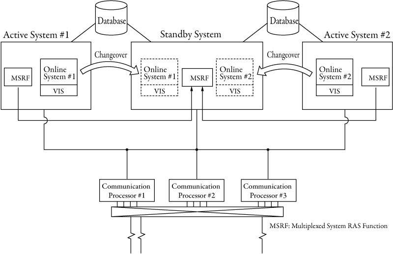
- (1) Hot standby system
- NEC realize a high-availability system that had a standby system equivalent to the running system and utilized system multiplexing to effect an automatic switchover between the two systems in the event of a halt or other problem, without the end user noticing the fault. This was achieved by using a multiplexed system RAS (Reliability Availability and Serviceability) function MSRF (Multi-System Ras Facility). See Figure 1 for an overview.
- (2) Scalability with various multiprocessor systems
- The OS enabled the user to use various high-reliability system modes including an advanced, loosely coupled multiprocessor system through the multi-database sharing function MDSF (Multi-System Database Sharing Facility), which allowed databases to be simultaneously updated by using a multi-system control processor MSCP (Multi System Control Processor), including up to 4 processors.
- (3) Pursuit of safety with an extended virtual computer function
- The VMX function, which enabled multiple virtual computers to operate on a single actual computer, allowed the user to run the current operation without the overhead of virtual computers and to perform development and evaluation of a new operation on a virtual computer.
2.2 Use in the Field of Scientific and Engineering Computation
- (1) Various functions to support large-scale scientific and engineering computation
- The OS achieved support that maximized hardware performance through the high-level language FORTRAN 77 for scientific and engineering computation, a 2GB virtual memory, an automatic vectorization function for an integrated array processor, and instruction reordering.
- (2) Engineering support system<.dt>
- Use of an integrated CEA system provided various design and analysis systems.
2.3 Expanded Network Functions
- (1) Multi-computer network
- The OS provided the multi-network function ATAM/MNF (Advanced Telecommunication Access Method/Multi Network Facility), which enabled inter-application communication between multiple host computers; job transfer; file transfer; pass-through; a micro mainframe link function that enabled optimal functional distribution between a personal computer or workstation and the host computer; and various other network functions between computers, including distributed operation.
- (2) Network support
- The OS provided a function to support the building of various types of communication networks, such as a network using a high-speed digital circuit or a communication satellite, and various C&C optical network systems. It also supported the building of a C&C videotex system, an inter-business information communication system and various VAN service systems.
See Figure 1 below.