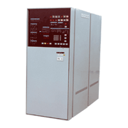
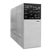
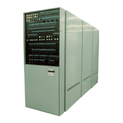
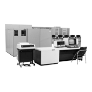
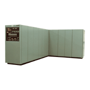
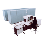
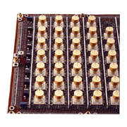
Development of the DIPS-11/5 Series as successor machines of the DIPS-11/10Series began at the research center of the Nippon Telegraph and Telephone Public Corporation (now NTT) in October 1977, with the aim of achieving a distributed processing system, securing leadership in technology, and strengthening competitiveness. More specifically, the work began as a development plan for the Model 15, 25, and 35 and involved improvement of the communication control processor (CCP), development of a new file control processor (FCP), introduction of features such as a 64-kilobyte chip memory, addition of a mid-size model (Model 5), and achievement of the processing capacity improvements needed for the successor machines of the DIPS-11 Model 10, 20, and 30. After about 1 year, additional development began on the Model 45 (the high-end model) as a DIPS ultra-high performance machine, so the Series was expanded to 5 models. This resulted in significant expansion of the performance range.
The Model 5 and FCP (the lower-end models) were developed by adding functions for file processing to the FCP to achieve sharing of hardware, such as register stacks for each level, dedicated instructions using firmware, and high-performance coupling capability with the CPU. Prototypes of the Model 5 and FCP were completed simultaneously in December 1979. Prototyping of the Model 15 and 35 finished in September 1980. For the Model 25, the plan was changed to a new design using high-performance logic LSI and high-density mounting technology throughout, and the prototype was finished in April 1981.
The DIPS-11 Model 45 was developed based on state-of-the-art technology: a 2-level buffer control system, main memory capacity expanded from 16 MB to 128 MB, and adoption of a service processor. A prototype achieving the world's highest level of performance was finished in March of 1982.
The 7400 Series CCPs were developed as CCPs for the DIP-11/5 Series. Two models -- the 7400CCP and 7410CCP-- were completed prior to 1980.
| Item | Model 5 (FCP) |
Model 15 |
Model 25 |
Model 35 |
Model 45 |
Note | |
|---|---|---|---|---|---|---|---|
| Performance (Model 10 ratio) |
0.8 | 1.5 | 2.4 | 3.1 | 8 | ||
| System | Number of CPUs | 1 | 2 | ||||
| Maximum main memory capacity (MB) | 8 | 16 | 128 | ||||
| Number of CHCs | -* | 4 | *Built into CPU |
||||
| Number of channels per CHC | 8 | 16 | |||||
| C P U | Number of instructions | 163* | 171 | 169 | 176 | *131 instruc- tions for FCP |
|
| Address conversion buffer (Number of entries) |
64x2 | 256x2 | 128x2 | 256x2 | |||
| Local memory capacity (KB) |
- | 16/32 | 32/64 | 32/64 | 64 | ||
| Buffer memory capacity (KB) |
- | - | - | - | 128/256/ 512* |
*Per MCU | |
| Main logic element | MECL10K | 200 gates 1200 gates LCML LSI |
100 gates ECL LSI |
400 gates 1300 gates ECL LSI |
|||
| M E M | Control unit (MB) | 8 | 32 | ||||
| Expansion unit (MB) | 1 | 2 | 2 (Initially 4) |
4 | |||
| Maximum throughput (MB/s) |
30 | 60 | 80 | 160 | 160 | ||
| Memory element | MOS memory (64 kb/chip) | ||||||
| D C H | Channel types | Burst mode channel, Multiplex mode channel | |||||
| CHC maximum throughput (MB/s) |
8 | 12 | 12 | 12 | 23 | ||


